Arduino 101: Find out more about this micro chip!
Arduino 101
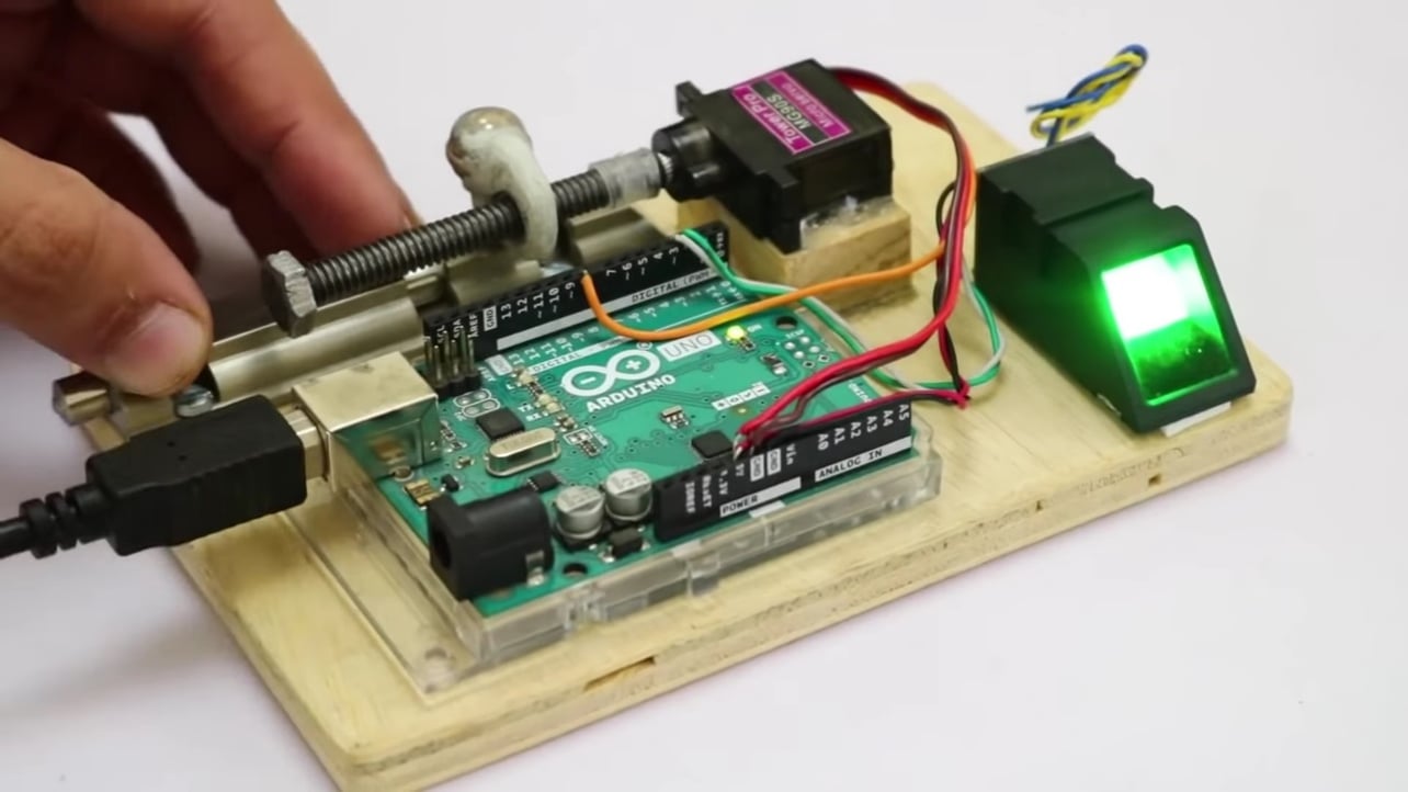
An Arduino is a microcontroller development board that is open source, you can use the Arduino to manipulate objects such as motors and lights, as well as read sensors. This essentially allows you to upload software and programs to this board, allowing them to interact with the actual objects in our lives. This allows you to create devices that respond and react as the others do in real life.
A temperature sensor, for instance, can be created to detect temperature and humidity. You can also create a PH sensor to measure the purity of water or the PH of different liquids. You can also create a pulse sensor.
More simply, if a device is monitored by a power supply, the Arduino can integrate with it in some way. And even if it isn’t powered by electricity, users can probably still integrate with it using motors and electromagnets.
The Arduino’s capabilities are practically unlimited. Therefore, a single tutorial can’t provide all the information you could ever need. That being said, we provide a basic outline of the essential knowledge and abilities required to get your Arduino working properly. This should serve as a starting point for additional research and education.
1-Arduino 101 (Arduino types)
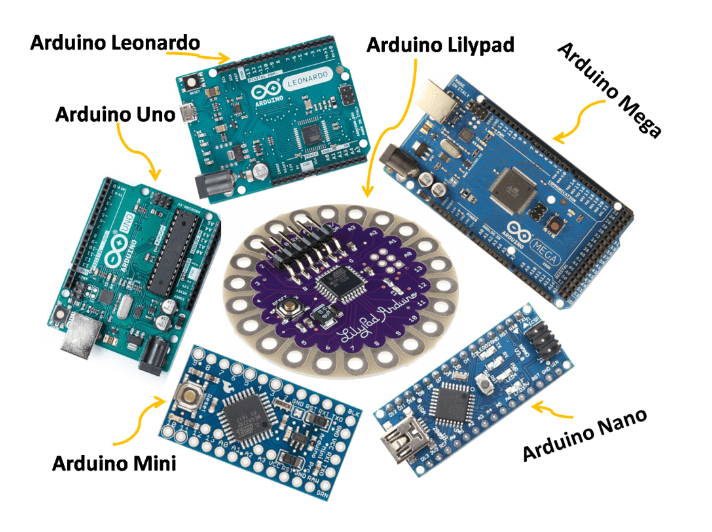
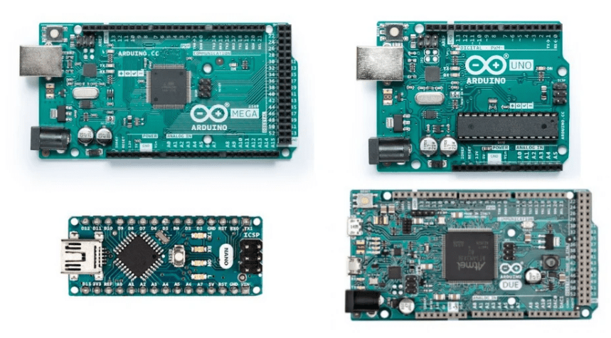
There are numerous Arduino concepts that you can choose from. This is a short rundown of some of the more frequent types of Arduino boards.
Arduino Mega 2560
In the family of Arduino devices, the Arduino Mega 2560 is the second most widely used model. The Arduino Mega resembles the larger, older brother of another type of Arduino called the Arduino Uno. It has a memory capacity of 256 KB, which is 8 times more than the Uno one. It also displayed 54 input and output pins, 16 of which were analog and 14 of which could perform PWM. All of the extra functionality, however, comes at the expense of a slightly larger circuit board. It will make your project more powerful, but it will also make it bigger.
Arduino Uno
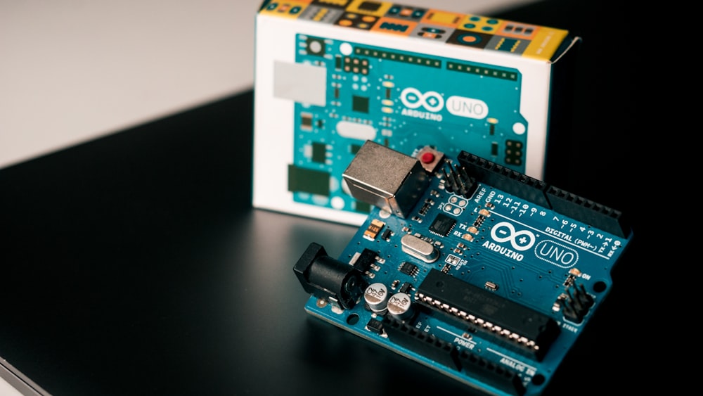
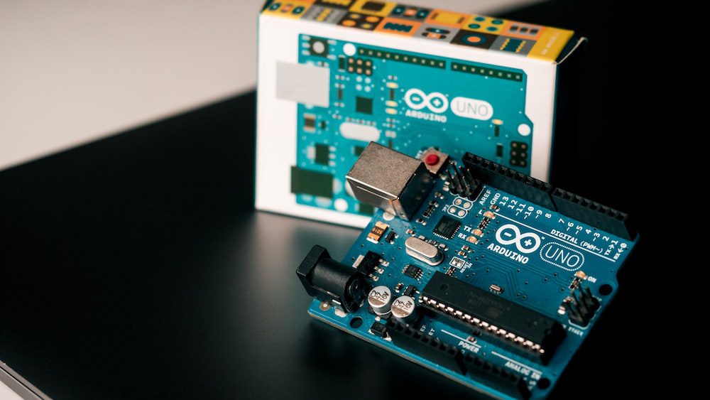
The Arduino Uno is the most popular version. When most people refer to an Arduino, they are referring to this board. The following step provides a more detailed breakdown of its features.
Arduino NG, Diecimila, and the Duemilanove (Legacy Versions)
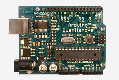
The NG, Diecimila, and Duemilanove are reputation copies of the Arduino Uno line of products. The key thing to remember about legacy boards is that they lack certain features found on the Arduino Uno. Some key distinctions include: the Diecimila and NG use ATMEGA168 chips rather than the more powerful ATMEGA328 chips; the jumper next to the USB port on the Diecimila and NG both requires manual selection between USB and battery power; and finally, before uploading a program to the Arduino NG, you must hold the rest button on the board for a few seconds.
Arduino Mega ADK
In essence, this particular Arduino is an Arduino Mega that has been tailored for interacting with Android smartphones. This is also a legacy version.
Arduino Yun
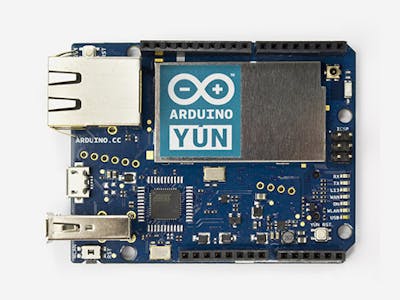
Instead of the ATmega328, the Arduino Yun utilizes an ATMega32U4 chip. What truly distinguishes it is the addition of the Atheros AR9331 microprocessor. This additional chip enables the board to run Linux in addition to the standard Arduino operating system. If all of that wasn’t enough, it also has built-in WiFi, In other words, you can code the board just like any other Arduino, while you can also access the internet via wifi by gaining access to the Linux side of the board. The Arduino and Linux parties involved can then easily communicate with one another. As a result, this board is incredibly strong and flexible. What you can do with this is only the tip of the iceberg.
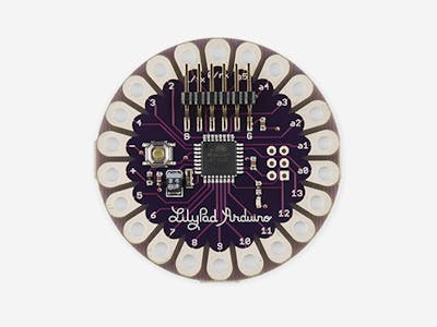
Arduino LilyPad
For wearable and electronic textile applications, the LilyPad was developed. It is meant to be sewn to fabric and then linked to other sewable elements with conductive thread. This board necessarily involves the use of an FTDI-USB TTL serial programming cable.
Arduino Nano
The Arduino Nano is the right choice if you want something smaller than the standard Arduino board. Based on a surface-mount ATmega328 chip, this version of the Arduino has a small footprint that allows it to fit into small spaces. It is also easily prototyping because it can be placed directly onto a breadboard.
2- Arduino UNO features
Some people often mistake the entire Arduino board for a microcontroller, but this is false. Using Atmel microcontrollers for programming and prototyping, the Arduino board is a specially created circuit board. The Arduino board is captivating because it is reasonably priced, plugs directly into a computer’s USB port, and is extremely simple to set up and use (compared to other development boards).
The Arduino UNO’s key characteristics include
- a layout that is open source. Because it is open source, it has a large community of people using and troubleshooting it. This makes finding someone to assist you in debugging your projects simple.
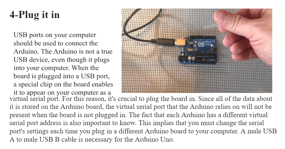
- a simple USB interface. The board’s chip plugs directly into your USB port and registers as a virtual serial port on your computer. Because of this, you can interact with it as if it were a serial device. This configuration has the advantage that serial communication is an incredibly simple (and tried-and-true) protocol, and USB makes connecting it to contemporary computers pretty handy.
- Power management is extremely simple, and voltage regulation is built in. An external power source of up to 12 v can be connected and regulated to 5 v and 3.3 v. It can also be powered directly from a USB port, eliminating the need for external power.
- a simple and inexpensive microcontroller “brain.” DigiKey sells the ATmega328 chip for about $2.88. It has a wide range of useful hardware features such as timers, PWM pins, external and internal interrupts, and multiple sleep modes.
- A clock with a frequency of 16 million hertz. This makes it a microcontroller that, while not the fastest available, is quick enough for the majority of applications.
- flash memory of 32 KB for storing your code.
- There are 13 digital pins and 6 analog pins. You can connect external hardware to your Arduino using these pins. For the Arduino to be used in the real world, these pins are essential. You can get started by simply inserting your gadgets and sensors into the sockets that match each of these pins.
- a serial device interface (ICSP connector) for connecting the Arduino without using the USB port. If your chip becomes corrupt and is unable to communicate with your computer, you will need to use this port to re-boatload it.
- A built-in LED is connected to digital pin 13 for quick and easy code debugging.
- A button to reset the chip’s program is included
3-Arduino IDE
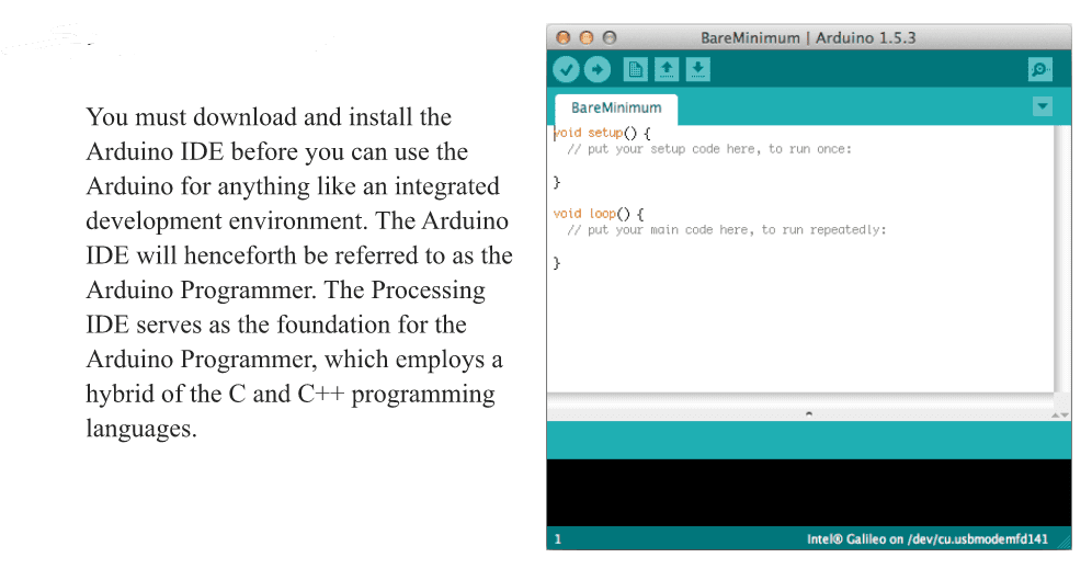
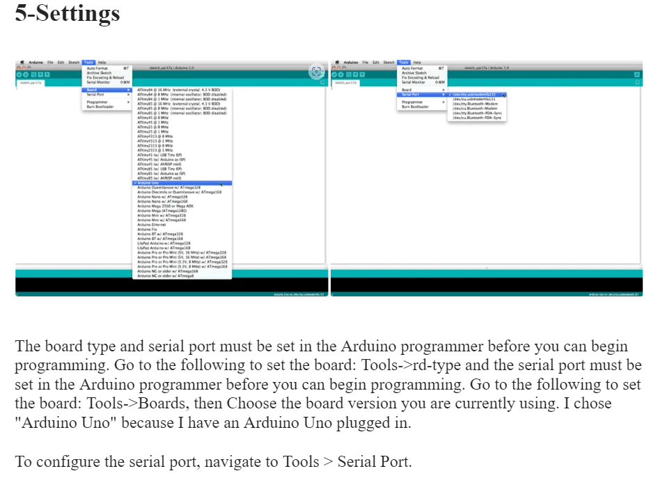
You must download and install the Arduino IDE before you can use the Arduino for anything like an integrated development environment. The Arduino IDE will henceforth be referred to as the Arduino Programmer.
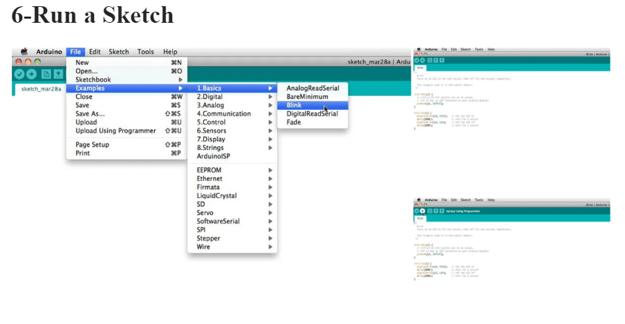
Arduino programs are referred to as sketches. There are many sample sketches already preloaded on the Arduino programmer. It’s brilliant because you can download any of these sketches and code the Arduino to act even if you’ve never coded anything before. Let’s load the blink example to make the LED connected to digital pin 13 blink on and off. You can find an example of a blink in (Files -> Examples -> Basics -> Blink).
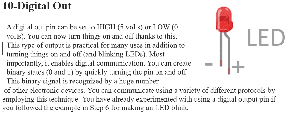
The test LED on the Arduino board is essentially turned on and off once every second by the blink example, which also sets pin D13 as an output. By pressing the upload button, which has the appearance of an arrow pointing to the right, after the blink example has been opened, it can be loaded onto the ATMEGA328 chip. Keep an eye out for the surface-mount status LED connected to Arduino pin 13 beginning to blink. By adjusting the delay time and pressing the upload button once more, you can alter the blinking rate.
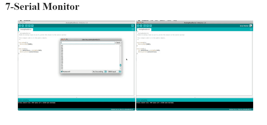
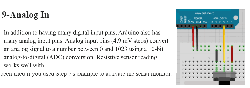
Your computer can communicate serially with the Arduino using the serial monitor. This is significant because it allows your computer to view data that your Arduino is receiving from sensors and other devices in real-time. To debug your code and comprehend what numerical values the chip is receiving, having this ability is invaluable. Connect the center sweep (middle pin) of a potentiometer, for example, to A0, and the outer pins to 5 V and ground, respectively. then publish this sketch (File –> Examples –> 1. Basics –> AnalogReadSerial) To activate the serial monitor, which resembles a magnifying glass, click the button. Now, the serial monitor’s analog pin can be seen reading the numbers. The numbers will increase and decrease as you turn the knob. The range of the numbers will be 0 to 1023. The analog pin converts a voltage between 0 and 5V to a specific number, which is the cause of this.
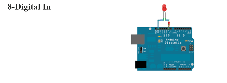
Analog and digital input pins are two distinct types of pins available on Arduino. Let’s look at the digital input pins first. The only two possible states for digital input pins are on and off. Other names for these two on and off states include “high” or “low,” “1 or “0,” “5V or “0V.” When a switch is opened or closed, this input is frequently used to detect the presence of voltage. Numerous digital communication protocols can be built on top of digital inputs. Binary signals, which are the foundation of all computing, can be produced by creating a 5V (high) or a 0V (low) pulse. This can be used to converse with other devices or digital sensors like a PING ultrasonic sensor. Connect a switch to digital pin 2, a 10K resistor to digital pin 2’s ground, and run the following code to see an easy example of a digital input in action (File –> Examples –> 2. Digital –> Button) A pull-down resistor is a resistor that connects the digital pin to ground when the switch is not pressed. The electricity no longer connects to the ground when the switch is pressed because the electrical connections inside the switch have less resistance than the resistor. The digital pin and 5V are the only two places where electricity flows. This is because electricity always takes the road less traveled.
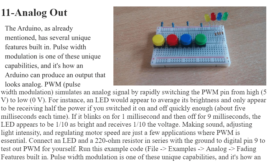
Arduino can produce an output that looks analog. PWM, or pulse width modulation, simulates an analog signal by rapidly switching the PWM pin between high (5 V) and low (0 V). For instance, an LED would appear to average its brightness and only appear to be receiving half the power if you switched it on and off quickly enough (about five milliseconds each time). If it blinks on for 1 millisecond and then off for 9 milliseconds, the LED appears to be 1/10 as bright and receives 1/10 the voltage. Making sound, adjusting light intensity, and regulating motor speed are just a few applications where PWM is essential. Connect an LED and a 220-ohm resistor in series with the ground to digital pin 9 to test out PWM for yourself. Run this example code (File -> Examples -> Analog -> Fading).
12-Write Your Code
You will need to learn some fundamental programming language syntax to write your code. For a programmer to understand your code, you must learn how to write it properly. This is comparable to knowing grammar rules and punctuation. Even if the book is written in English, no one will be able to understand it if the grammar and punctuation are incorrect. When writing your code, keep the following in mind: An Arduino sketch is a piece of software. An Arduino sketch’s entire body of code is executed. Five sections make up most Arduino sketches.
- The header of the sketch typically states what the sketch is about and who wrote it.
- Global variables are then typically defined after that. This is where the various Arduino pins are frequently given constant names.
- The setup routine for the Arduino starts once the initial variables have been set. When setting initial conditions for variables, we run any preliminary code that we only want to run once in the setup function. The start of serial communication occurs here, which is necessary for the serial monitor to function.
- We move on to the loop routine from the setup function. This is the sketch’s main routine. Not only will your main code be executed here, but it will also be repeated as long as the sketch is running.
- Frequently, there are additional functions listed below the loop routine. The setup and loop routine is the only place where these user-defined functions are activated. The Arduino executes all of the function’s code from top to bottom when one of these functions is called, and it then moves on to the sketch’s next line, where it left off when the previous function was called. The benefit of functions is that you can run common procedures repeatedly without having to write the same lines of code. Because a function routine is only written once, you can simply call it more than once to release memory from the chip. Additionally, it facilitates reading code.
Despite this, only the Setup and Loop routines are required to be present in the sketch. The Arduino Language, which is roughly based on C, is required for writing code. The Arduino language requires that almost all statements end with pres. A is not required for conditionals (such as if statements and for loops); On the Arduino Language page, conditionals are listed under “Control Structures” and have their own set of rules. The places where numbers are stored are called variables. Variables allow for the entry and exit of values. Before being used, variables must first be defined (stated in the code) and have a corresponding data type.
Assume we want to write code that reads a photocell connected to pin A0 and uses the reading to control the brightness of an LED connected to pin D9.
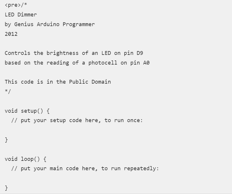
Open the BareMinimum sketch first by going to the following address (File -> Examples -> 1.Basic -> BareMinimum), which looks like this:
Let’s add a header to the code next, so that others will understand what we are creating, why we are creating it, and under what conditions:
Let’s define the pin names and create variables after that is settled.
<pre>/*
LED Dimmer
by Genius Arduino Programmer
2012
Controls the brightness of an LED on pin D9
based on the reading of a photocell on pin A0
This code is in the Public Domain
*/
// name analog pin 0 a constant name
const int analogInPin = A0;
// name digital pin 9 a constant name
const int LEDPin = 9;
//variable for reading a photocell
int photocell;
void setup() {
// put your setup code here, to run once:
}
void loop() {
// put your main code here, to run repeatedly:
}
Let’s write the code now that the variables and pin names have been set:
<pre>/*
LED Dimmer
by Genius Arduino Programmer
2012
Controls the brightness of an LED on pin D9
based on the reading of a photocell on pin A0
This code is in the Public Domain
*/
// name analog pin 0 a constant name
const int analogInPin = A0;
// name digital pin 9 a constant name
const int LEDPin = 9;
//variable for reading a photocell
int photocell;
void setup() {
//nothing here right now
}
void loop() {
//read the analog in pin and set the reading to the photocell variable
photocell = analogRead(analogInPin);
//control the LED pin using the value read by the photocell
analogWrite(LEDPin, photocell);
//pause the code for 1/10 second
//1 second = 1000
delay(100);
}
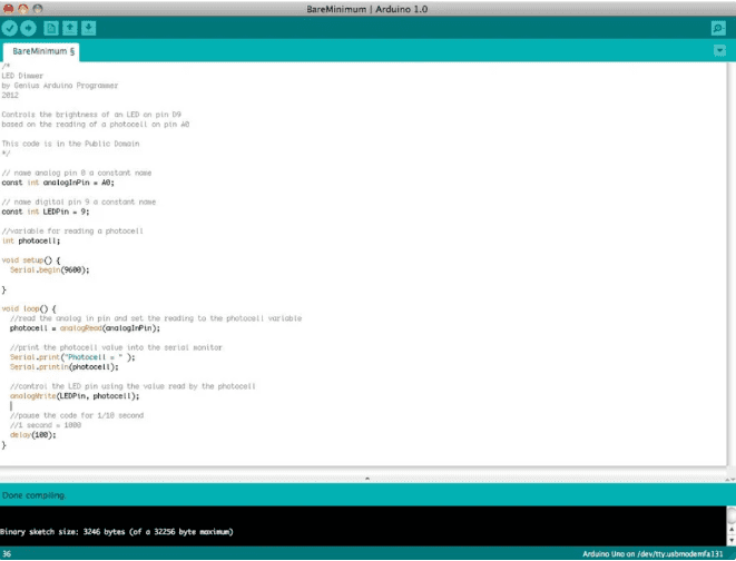
We must use the serial monitor to see the numbers the analog pin is detecting from the photocell. Let’s open the serial port and display those figures:
<pre>/*
LED Dimmer
by Genius Arduino Programmer
2012
Controls the brightness of an LED on pin D9
based on the reading of a photocell on pin A0
This code is in the Public Domain
*/
// name analog pin 0 a constant name
const int analogInPin = A0;
// name digital pin 9 a constant name
const int LEDPin = 9;
//variable for reading a photocell
int photocell;
void setup() {
Serial.begin(9600);
}
void loop() {
//read the analog in pin and set the reading to the photocell variable
photocell = analogRead(analogInPin);
//print the photocell value into the serial monitor
Serial.print(“Photocell = ” );
Serial.println(photocell);
//control the LED pin using the value read by the photocell
analogWrite(LEDPin, photocell);
//pause the code for 1/10 second
//1 second = 1000
delay(100);
}
Shields are expansion adapter boards that can be plugged on top of the Arduino Uno to add additional functionality. Because the Arduino is open hardware, anyone with the desire can design an Arduino shield for any purpose. Because of this, there are countless Arduino shields in use today. The Arduino Playground has an ever-expanding list of Arduino shields. Remember that there are more shields available than are listed on that page, and as always, Google is your friend.
14- Building an External Circuit
image source @ Arduino
You will want to create your circuits to interface with the Arduino as your projects become more complicated. The Internet is an incredible resource for electronic knowledge and circuit diagrams, though you won’t learn electronics overnight.
15- A step further
making some projects is the only thing left to do from here. Online, there is a tone of fantastic Arduino tutorials and resources.
Arduino 101
